Survey of London: Volumes 43 and 44, Poplar, Blackwall and Isle of Dogs. Originally published by London County Council, London, 1994.
This free content was digitised by double rekeying. All rights reserved.
'Southern Blackwall: The Blackwall Tunnel', in Survey of London: Volumes 43 and 44, Poplar, Blackwall and Isle of Dogs, ed. Hermione Hobhouse (London, 1994), British History Online https://www.british-history.ac.uk/survey-london/vols43-4/pp640-645 [accessed 30 April 2025].
'Southern Blackwall: The Blackwall Tunnel', in Survey of London: Volumes 43 and 44, Poplar, Blackwall and Isle of Dogs. Edited by Hermione Hobhouse (London, 1994), British History Online, accessed April 30, 2025, https://www.british-history.ac.uk/survey-london/vols43-4/pp640-645.
"Southern Blackwall: The Blackwall Tunnel". Survey of London: Volumes 43 and 44, Poplar, Blackwall and Isle of Dogs. Ed. Hermione Hobhouse (London, 1994), British History Online. Web. 30 April 2025. https://www.british-history.ac.uk/survey-london/vols43-4/pp640-645.
In this section
The Blackwall Tunnel
The Blackwall Tunnel was built by the LCC between 1892 and 1897 in response to the growing need for improved free road communications across the Thames in the East End. When the Metropolitan Board of Works (MBW) was created in 1855 there were only three free cross-river routes in London, at Westminster, Blackfriars and London Bridges. By 1880 all of the other road bridges downstream from Chiswick had been freed from toll, (fn. 3) but there was still no provision for the two-fifths of London's population living east of London Bridge. During the late 1870s and early to mid-1880s the MBW promoted various unsuccessful Bills for a new crossing. Eventually, in 1885, an Act was obtained authorizing the construction of Tower Bridge by the City Corporation, and this was followed in 1887 by the MBW Thames Tunnel (Blackwall) Act, which empowered the Board to build a new crossing between Blackwall and Greenwich. (fn. 4)
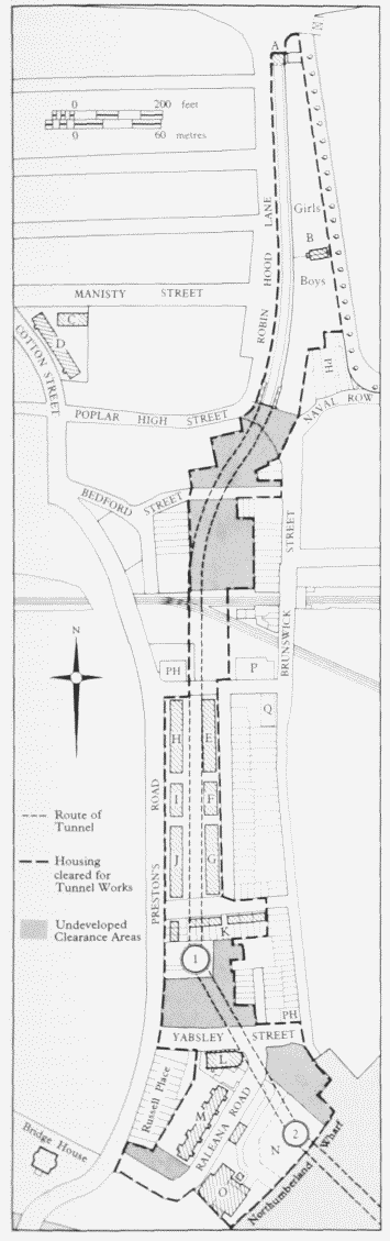
Blackwall Tunnel. Plan of c1904 showing the route of the northern end of the tunnel, the extent of the area cleared and developments associated with the tunnel scheme Key: 1, 2 Tunnel Shafts: A Entrance Gatehouse: B Tunnel Gardens: C Toronto Buildings: D Montreal Buildings: E Winnipeg Buildings: F Hudson Buildings: G Ontario Buildings: H Quebec Buildings: I Baffin Buildings: J Ottawa Buildings: K St Lawrence Cottages: L St Nicholas's Church: M Council Buildings: N Raleigh Playground: O Electric Lighting Station: P Midland Railway Hydraulic Pumping Engine House: Q Midland Railway Offices: PH public house
Sir Joseph Bazalgette, the MBW's Engineer, prepared a scheme comprising separate tunnels for vehicles and pedestrians. (fn. 5) However, with the transfer of municipal power to the LCC in March 1889, a new plan was prepared by Alexander Binnie, the LCC Engineer, for a single tunnel large enough to accommodate two lines of vehicles and foot-passengers. This was approved by the LCC in 1891, and the tender of S. Pearson & Son of Victoria Street, at £871,000, was accepted for its construction. (fn. 6)
Design and Construction
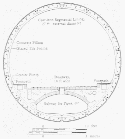
Binnie's designs for the tunnel and the engineering techniques used - tunnelling shield, compressed air and cast-iron rings - followed the same principles as J. Henry Greathead's City and South London Railway Tunnel of 1886–90 and two large contemporary tunnels: the Hudson River Tunnel in New York, begun in 1879, and the St Clair Tunnel in Canada, begun in 1889. However, at over 6,000ft long, and with an external diameter of 27ft (to accommodate a roadway 16ft wide, with two footpaths), Binnie's was the largest sub-aqueous tunnel yet built, and was a bold undertaking considering the difficult subsoil at Blackwall.
The tunnel route was planned to connect East India Dock Road with Woolwich Road, crossing the Thames between Northumberland Wharf on the north and Ordnance Wharf on the south. The proximity of the docks and the availability of suitable approaches dictated its slightly sinuous path. (fn. 7) Four vertical shafts were situated where there was to be a change in line or level, the tunnel running straight between them, save for an extra bend on the northern side to avoid a main sewer and some housing in Bedford Street (fig. 243). The tunnel shafts enormous double-skinned cylinders of iron - were constructed by the Thames Iron Works & Ship Building Company of Blackwall, (fn. 8) and lined inside with glazed brickwork (Plate 109a). Shafts Nos 1 and 4 were eventually fitted with spiral staircases for pedestrians, and domed over with glass-and-iron roofs. The other two shafts were reserved for administrative and working purposes (No. 2), and for ventilation (No. 3). Damaged by bombing during the Second World War, in the late 1960s the shafts were reconstructed in brick and concrete with shallow-domed roofs of concrete slabs as part of the improvements to the tunnel and the redevelopment of Northumberland Wharf. (fn. 9)
Blackwall Tunnel, section showing the construction
The Blackwall scheme was divided into three separate and distinct sections: open approach roads with concreteand-brick retaining walls; cut-and-cover sections lined with concrete and white-glazed bricks; and the cast-iron tunnel, 3,083ft long, 1,220ft of which lay directly beneath the river.
The tunnelling shield used at Blackwall was designed by E. W. Moir, the contractors' engineer, and was built by Easton & Anderson of Erith. (fn. 10) It was a development of the design introduced by Marc Brunel for the Thames Tunnel of 1825–43, and improved upon by Greathead for the Tower Subway of 1869 and the City and South London Railway Tunnel of 1886. A giant steel cylinder over 19ft long, the shield was divided into sections to allow as many as 12 men to make a simultaneous assault on the work-face (fig. 246). The cast-iron lining was assembled at the back of the shield and lifted into position by hydraulic arms and secured in place by a solid bed of cement 'grouting'. The interior was lined with 14ins of Portland-cement concrete and faced with a granite plinth and white-glazed tiles specially designed for the tunnel by T. & R. Boote of Burslem (fig. 244). Granite sets were used to pave the tunnel roadway, except in the section beneath the river, where asphalt was used. The outer ring of the shield was left embedded in the tunnel as a permanent memorial. (fn. 11) Compressed air was used in the tunnel during construction to prevent an inrush of water from above. Safe levels of compression required the tunnel to pass in places within 5–6ft of the river bed, with only loose shingly ballast and gravel between the heads of the workmen and the murky Thames above. Compensation was arranged for any workmen injured while working in compressed air and for the families of any men killed, and hospital facilities were also provided. (fn. 12)
Progress of the Work
Work on the tunnel began in March 1892. By the end of the year two teams of workmen were excavating the approaches on both sides of the river, while a third was driving piles into the river bed at Northumberland Wharf, reclaiming land for the site of No. 2 Shaft. (fn. 13) (The wharf was extended into the river to accommodate the tunnel shaft, and a new concrete wharf wall was erected and extended to meet the wall of the new Blackwall Entrance lock.) Tunnelling proper started in the easier ground south of the Thames, and work began on the main river portion on the Kent side in September 1893. To prevent compressed air from 'blowing-out' of the tunnel beneath the Thames, a large artificial bed of clay 10ft thick and 150ft wide was dumped from hopper barges on to the river bed. (fn. 14) Although some minor works were still to be completed, the tunnel was officially opened by the Prince and Princess of Wales on 22 May 1897. Most of the vehicles using the tunnel during the first weeks were dock and railway vans, and the new crossing became popular with local workers on both sides of the river. (fn. 15)
Surprisingly few of the people connected with the Blackwall Tunnel were Londoners. Although the LCC asked Pearsons to employ local workmen, (fn. 16) the foremen came from the provinces, particularly Yorkshire. The iron tunnel lining was made in Glasgow by the British Hydraulic Foundry Company, the bricks and tiles came from provincial firms, the granite sets were from Aberdeen, and the asphalt roadway was laid by teams of Italian workmen employed by the French Val de Travers company. Alexander Binnie had been the LCC's Chief Engineer throughout, with David Hay and Maurice Fitzmaurice as Resident Engineers, and E. W. Moir representing the contractors. (fn. 17) The Blackwall Tunnel was the only free road-crossing of the Thames available between Tower Bridge and the Woolwich Free Ferry (a distance of nearly nine miles), and its construction had been so successful that, at the time of its completion, the LCC was already planning another large sub-aqueous vehicular tunnel at Rotherhithe, and a smaller foot-tunnel linking Greenwich with Island Gardens (see page 525).
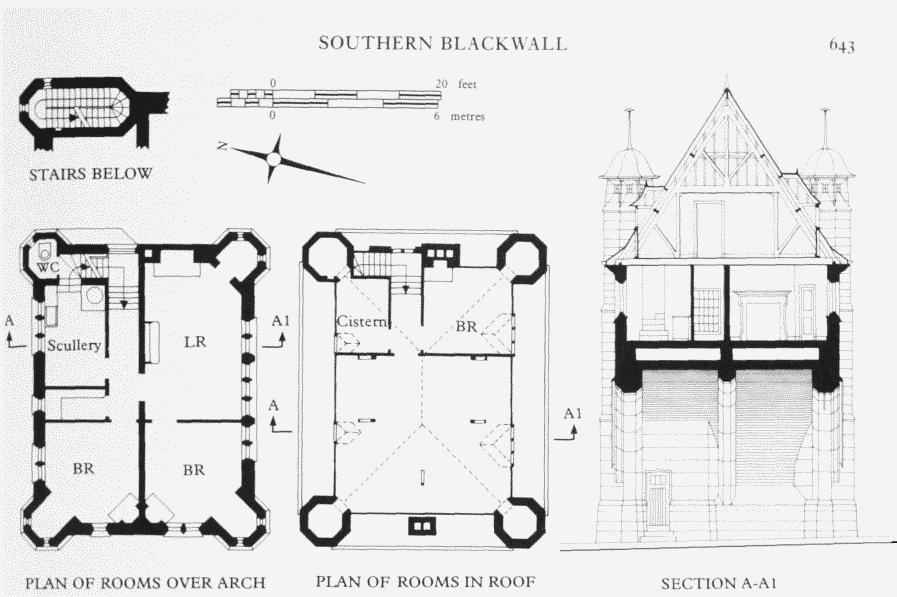
Blackwall Tunnel, plans and section of the north entrance gatehouse. Thomas Blashill, LCC Architect, 1896–7. Demolished
Ancillary Buildings
Entrance Gatehouses.
Binnie's original plans included designs for a pair of simple Classical arches to mark the entrances to the open approach roads and indicate the maximum headroom in the tunnel. These were superseded by more ambitious designs by Thomas Blashill, the LCC Architect, for two entrance gatehouses to accommodate the superintendent and caretaker of the tunnel (Plates 109b, 110b). (fn. 18)
The north gatehouse was erected in 1896–7. Basically rectangular in plan, with octagonal turrets at each corner, it spanned the open approach road, with two bedrooms, a living-room, scullery, larder and w.c. on the floor above the archway (fig. 245). A third bedroom and a cistern room occupied part of the roof space above. The houses were built of light-brown sandstone with contrasting bands of red sandstone. Pearson & Son were the contractors, but appear to have sub-contracted the work to Dove Brothers. (fn. 19) The facades were decorated with shields carrying the coats of arms of Middlesex, Kent, Essex and Surrey, and commemorative bronze plaques by Singer & Son of Frome. The gatehouses provided unusual Art Nouveau silhouettes amid the working-class housing of Poplar and the empty expanses and gas-storage tanks of Greenwich Marshes, and the proximity of the East India Dock Gateway on the north side no doubt inspired Blashill to compete with it in architectural terms.
In 1899 public toilets were provided by the LCC in a small building adjoining the north entrance gatehouse, in a suitably sympathetic style. (fn. 20)
In 1958 the north entrance house and the toilets were demolished during work on the approaches for the new Blackwall Tunnel. The south gatehouse at Greenwich still stands.
Tunnel Entrance Bridge Parapets
The entrance facades to the cut-and-cover portions of the tunnel had fronts of polished red granite, with two flights of stone steps leading up to the roadway to provide easy access for local foot passengers. The design was kept simple, the only surface decoration being fleur-de-lis finials on the piers and an inscription along the top of the parapet marking the completion of the runnel. Ornamental electric lamps were provided on the staircases. Most of the parapet on the north side still remains today, although the stone steps and attached walls and piers were demolished.
Blackwall Tunnel Electric Lighting Station,Northumberland Wharf (demolished)
Since no public supply of electricity was available to light the tunnel and its buildings, (fn. 21) the LCC decided in 1896 to build an electricity-generating station at Northumberland Wharf, adjoining Shaft No. 2 (fig. 243). (fn. 22) This comprised buildings to house the boilers and engines, a large fluted chimney (120ft high and 12ft square at its base), a subterranean water-tank, and a combined building for offices and stores (Plate 110a). Designed by the LCC Engineer's Department and constructed in stock brick by Pearson & Son, (fn. 23) the buildings were of a plain, Italianate style, with a main fenestration of round-headed windows coupled in arched recesses. The boilers and fittings were supplied by Fraser & Fraser, and the engines and dynamos by Laing, Wharton & Down. (fn. 24) The buildings were finished by mid-July 1897, when the tunnel opened for continuous day-and-night traffic. (fn. 25) (fn. 1)
The plant was shut down in 1912 when the tunnel was connected to the municipal supply, and in 1920 the wharf and disused station were sold to Poplar Borough Council for £11,000, and were then used as a refuse depot. (fn. 27) The buildings were demolished during redevelopment by the GLC in the late 1960s. (fn. 28)
Blackwall Tunnel Duplication
Although adequate for the predominantly horse-drawn traffic of the nineteenth century, the tunnel could not meet the growing demands of twentieth-century London's motorized traffic. In 1937 the LCC decided to build a second tunnel c800ft downstream of, and running parallel to, the existing tunnel. The new tunnel was to be for south-bound vehicles only, with the existing tunnel serving north-bound traffic and pedestrians. Improved approach roads would require the demolition of, amongst other things, the tunnelentrance gatehouse and Tunnel Gardens. (fn. 29) The LCC (Tunnel and Improvements) Act of 1938 (fn. 30) authorized the duplication of the tunnel and the acquisition of land and demolition of property, but the Second World War and the economic stringency which followed it delayed work on the scheme until 1957, when the Ministry of Transport authorized the LCC to begin work on the new northern approach road and proceed with necessary improvements to the old tunnel. Work began in April 1958. (fn. 31)
The Northern Approach Road, 1958–60.
A new road was designed for eight lanes of traffic, with two central carriageways passing beneath the East India Dock Road, and slip roads on either side. It was hoped that this 'semiclover-leaf interchange' would allow for an uninterrupted traffic flow into and out of the tunnel and along East India Dock Road, (fn. 32) but the Blackwall Tunnel remains notorious for long delays. The new scheme also required the construction of new roads and the upgrading of existing roads linked with the approach. A new entrance to the East India Docks was constructed, and the dock wall was renovated and realigned. A joint tender of £570,191 from Holland, Hannen & Cubitts and Fitzpatrick & Son was accepted by the LCC for the northern approach works. (fn. 33) The new approach road was opened on 27 June 1960, (fn. 34) and work then began on the second tunnel.
The New Blackwall Tunnel.
The route of the new tunnel was determined largely by the availability of suitable sites to house the two caissons which would form the permanent ventilation shafts. Sites were selected in part of the South Eastern Gas Board's works at Greenwich and in the former Midland Railway's dock at Blackwall Yard on the Poplar side of the river. Rectangular caissons of concrete and steel plate were sunk on either side of the river and two Greathead shields (previously used in the construction of the Dartford Tunnel) were reconditioned and assembled in the caissons. A special chemical compound was used to secure the surrounding water-bearing strata before tunnelling began, and the shields finally met beneath the river in May 1964. (fn. 35)
The cast-iron tunnel was designed by Mott, Hay & Anderson, and built by Balfour, Beatty & Company. Subcontractors for the specialist ground treatment were the Cementation Company and Soil Mechanics-Soletanche Ltd. The cut-and-cover and open approach sections were designed by the LCC's Chief Engineer's Department, with assistance from M. H. Ionys Hughes, Consulting Engineer, on the design of the open approaches. Watertight reinforced-concrete was used throughout and the contractors for this section were Kier Limited. Various linings were used throughout the length of the new tunnel, including Portland stone, precast tiled panels and black terrazzo coping. The cast-iron sections were lined with light-grey PVC-coated aluminium sheeting, with a suspended ceiling of the same material in dark blue.
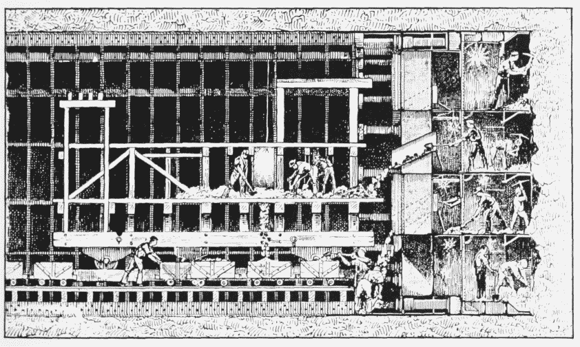
Blackwall Tunnel. Longitudinal section of the tunnel under construction, with the shield at work in the clay. The cylindrical steel shield enabled up to 12 men to excavate the work-face simultaneously. The shield was then driven forward by hydraulic arms and rings of cast-iron, forming the tunnel-lining, were put in place in the space left behind
Contractors for the tunnel lining, roadway and services were Balfour, Beatty & Company. The final cost of construction of this stage of the project was approximately £7 million. (fn. 36)
The tunnel was opened on 2 August 1967 by Desmond Plummer, Leader of the GLC, at a special double ceremony that also included the inauguration of work on the Blackwall Tunnel Southern Approach. (fn. 37) (fn. 2) The old tunnel was then closed for improvements. It was reopened on 4 April 1969 with a new electronic signalling system designed to redirect 'overheight' traffic. A month later the tunnel was finally closed to pedestrians. (fn. 39)
Ancillary Buildings.
A squat, rectangular administration building was constructed between the two approach roads on the Poplar side of the river, near the entrance to the new tunnel. It is of concrete, on two levels. Offices and a traffic-control room occupy the upper level, with a garage and yard for maintenance vehicles below. The contractors were William J. Jerram, and building costs were £87,300. (fn. 40)
The ventilation plants and electrical equipment for the second tunnel required two new buildings. The curvilinear plan resulted partly from the need to enclose four large circular fan housings and motors, and, similarly, the tall aerodynamic air flows of the fans influenced the sculptural elevation of the shafts (Plate 110c). The roof section consists of a shell of sprayed concrete on a framework of stressed cables, and is supported by a ground-floor section of Staffordshire blue brick and glazing, surrounded by three successive levels of precast flags, brick paving and asphalt paving. The buildings were designed by the GLC's Department of Architecture and Civic Design and constructed under its supervision by William J. Jerram. The ventilation plants were the work of the Midland Heating & Ventilation Company of Birmingham, and the combined cost for the buildings and ventilation plants was £360,000. (fn. 41)